Mini Split Thermistor Test: How to Check Temperature Sensors on Ductless Heat Pumps
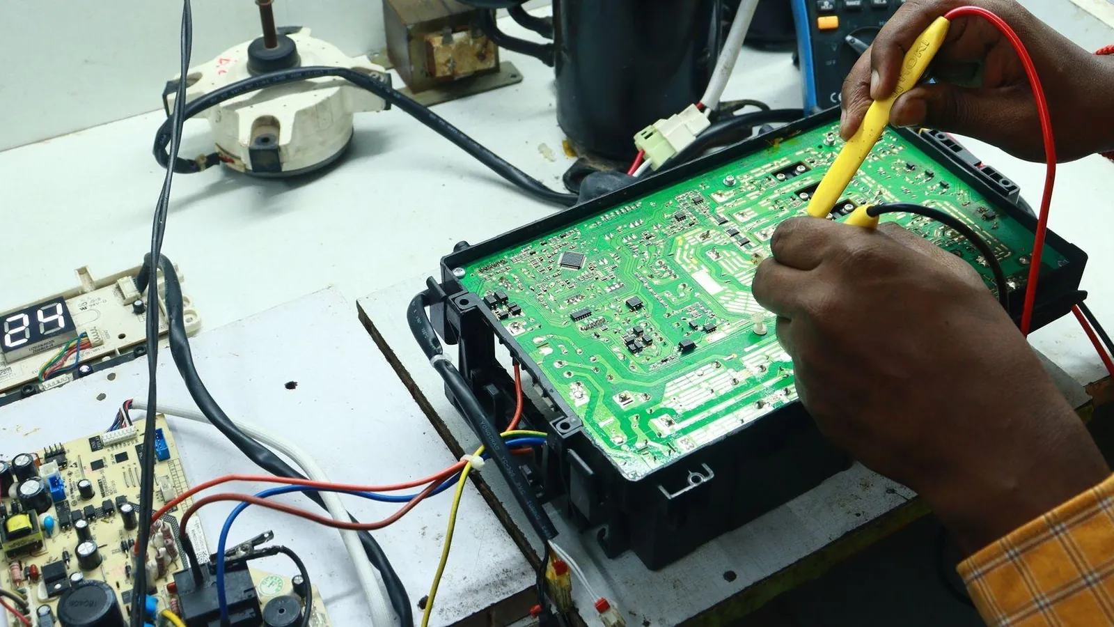
A mini split thermistor test can tell you why your ductless heat pump won't heat, won't cool or keeps flashing that same error code every time you reset it. The problem might just be a small sensor that costs a few dollars, not the compressor or the charge of refrigerant. Here's how you can test it yourself before you call anyone in.
Key Takeaways
-
A mini split thermistor is a temperature sensor that changes resistance as the temperature changes, and its resistance goes up or down with the temperature. When it fails - whether that is open, shorted or off - the control board can shut the system down or keep throwing the same error codes.
-
When the resistance does not match the chart within 7% to 10%, the sensor is off and you should replace it.
-
You can test and replace plug-in or clip-on sensors yourself. But anything that involves the refrigerant circuit, PCB soldering work or sensors that are sealed into the coil is work for a licensed service tech.
What a Mini Split Thermistor Does
A thermistor is the mini split's temperature sensor - a small two-wire part that sends a temperature reading back to the control board. Thermistors are temperature sensors that change resistance as the temperature changes. Most mini split systems use NTC (negative temperature) thermistors, which means the resistance drops as the sensor gets warmer and goes up as it gets cooler. NTC thermistors are common in HVAC systems because they respond faster than older temperature sensors, and that matters when the board needs to respond quickly to coil frost or compressor overheating.
For temperature input, the thermistors connect to control boards, and the board uses that input to run almost everything. On a typical ductless system, you'll find thermistors in several spots:
-
Indoor room air sensor - it sits in or near the return grille and reads the room temp against the setpoint.
-
Coil (evaporator) sensor - it is clipped to the indoor coil and monitors for frost buildup or coil outlet temperature.
-
Discharge air sensor - sometimes mounted downstream of the coil.
-
Outdoor ambient sensor - it reads outside air temperature.
-
Outdoor coil / discharge pipe sensor - it monitors condenser coil or compressor discharge for overheat or defrost timing.
Common bad-thermistor symptoms
When a sensor fails or goes out of range, you'll often see one or more of these problems:
-
Even though the setpoint on the remote is right, the indoor fan runs but you get no heating or cooling.
-
The unit short-cycles or misses the temperature - it runs too long or shuts off too early.
-
In heat mode, the system won't come out of defrost and gets stuck in a defrost loop.
-
On very hot or very cold days, the unit won't start because the sensor tells the board the outdoor temp is outside the safe range.
-
After you reset power at the breaker, the same error code comes back.
Sensor-related error codes
If you look up your error code, you'll often find it points to a specific sensor. For example, MRCOOL's service manual lists codes EH 60, EH 61, EC 52, EC 53, EC 54 and EC 56 - all of them trigger when the thermistor's voltage falls below about 0.06 V or rises above 4.94 V. That voltage range is what an open or shorted thermistor looks like to the board.
- Other brands (Fujitsu, Mitsubishi, Daikin, Haier) handle sensor faults in a similar way, but the actual code letters and numbers vary by brand and model. Always check the sticker on your unit and the specific manual before you assume a code means the same thing across different product lines.
Test a Mini Split Thermistor
What you need
- Digital multimeter with a resistance (ohms) setting - you'll measure electrical resistance in ohms using a multimeter set to the kΩ range.
Get the right chart first
Testing a thermistor needs the right thermistor chart. Each brand - and often each model within a brand - publishes its own resistance-vs-temperature table in the service manual, not the owner's manual. Download it before you start. For example, Daikin's wall-mount service manuals include a full resistance table for each sensor in the unit. If you can't find yours online, a mini split training forum or the manufacturer's tech support line can usually help you track it down.
Step-by-step test procedure
To test a mini-split thermistor, you turn off power and disconnect the sensor from the control board. Here's the full sequence:
-
Kill power. Turn off the disconnect or breaker feeding the indoor unit and wait a few minutes for any capacitors on the inverter board to bleed down.
-
Open the unit. Remove the indoor unit's front cover and any small PCB cover so you can get to the control board and sensor plugs. It's usually a couple of screws or plastic clips.
-
Photograph everything. Before you unplug a single wire, take photos of the connector positions and wire routing. This saves you from a wiring question later on.
-
Identify the thermistor connector. Using the wiring diagram on the unit's door sticker or in the service manual, find the specific sensor you are after - room air, coil or outdoor. Each plug is usually labeled on the board silkscreen (like RT1, RT2, TH1).
-
Unplug the sensor from the board. Remove power and test thermistors disconnected from control boards - this is critical. If you leave the plug in, you'll read the board's internal circuitry in parallel with the sensor and the number will be wrong.
-
Measure the temperature that the thermistor senses. Hold a thermometer near where the sensor is. For a room sensor, room temperature works. For a coil sensor, measure the ambient temp near the coil (the unit is off, so the coil should be close to room temp).
-
Set your meter. Switch the multimeter to the kΩ resistance range. Read the resistance through the thermistor's two wires by placing one probe on each pin of the unplugged connector. Hold steady for a few seconds until the reading stabilizes.
-
Compare resistance readings to the thermistor chart. Look up the temperature you just measured and find the expected resistance. Typical residential mini-split thermistors have a resistance of 10 kΩ at 25°C (about 77°F). At freezing (0°C / 32°F), the same sensor might read 30 kΩ or higher. At 40–45°C (104–113°F), it could drop to 4–6 kΩ. Your model's chart is the authority - these are just ballpark figures so you know what range to expect.
-
Optionally test at a second temperature. Gently warm the sensor with your fingers or a hair dryer on low from a safe distance, or cool it with an ice pack wrapped in a cloth. Watch for a smooth, continuous resistance change. NTC sensors are common in HVAC thermistor testing because they respond predictably to temperature shifts.
-
Reconnect and reassemble. Once you are done, push the thermistor plug firmly back into the board and put the panels back on.
Pass or fail?
Here's how to read your results:
| What the meter shows | What it means |
|---|---|
| Reading close to the chart value, changes smoothly when warmed or cooled | Sensor is good |
| 0 Ω or very low resistance | A short circuit reading indicates a shorted thermistor or wiring |
| "OL" or infinite resistance | An open circuit reading indicates a broken internal wire |
| Reading more than 7–10% off the chart at room temp | Sensor has drifted - it may work intermittently but will cause erratic behavior |
| Reading jumps around or cuts out when you wiggle the leads | Internal break or bad splice in the wire |
If readings fall outside the range on the chart, replace the thermistor. Parts are usually inexpensive - often under $15 - and available by part number from the manufacturer or aftermarket suppliers.
DIY vs. Pro Repairs
- Service tech territory: Sensors potted into the coil, sensors that are part of a larger sealed harness, a sensor code that persists even with a known-good sensor (which likely means a PCB fault), and any work requiring refrigerant recovery or re-brazing. That last category is EPA 608 work - not a DIY job.
You can use an error code lookup to figure out the fault for your brand, confirm which sensor is involved, and then come back to this procedure to test it. Having the exact code and which sensor it is saves time whether you fix it yourself or hand the information to a technician.
Safety note: Stay away from live terminals. Never probe sensors with power on unless the factory procedure calls for a voltage check. Working around control boards or high-voltage inverter components is not something everyone is comfortable with, so call a pro if you are not. There is no shame in knowing your limit.
When Thermistor Testing Points to Bigger Problems
Sometimes the thermistor tests perfectly - the resistance matches the chart and changes smoothly - but the mini split still gives sensor-related error codes. That usually means the problem is before or after the sensor itself: the wiring, the control board or even the refrigerant system.
Real-world diagnostic example
On a Mitsubishi MSZ-FX, pressing the E.O. switch starts a 30-minute test run - press once for COOL, twice for HEAT. If the upper operation light blinks every 0.5 seconds during the test, the first suspect is the indoor/outdoor connecting wire, not necessarily the thermistor itself. That link between indoor and outdoor boards carries sensor data, and a bad connection there can act like a sensor fault even when the sensor is fine.
Board and display issues
-
If the sensor tests normal at the plug but the same code keeps coming back, a failing indoor PCB is likely. The board's analog-to-digital converter may not be reading the voltage divider correctly, even though the thermistor's resistance is spot-on.
-
On MRCOOL units, if the display shows a garbled or undefined code that does not match the error table, test with the remote. If the indoor unit doesn't respond, replace the indoor PCB. If it does respond, the display board is the problem.
Refrigerant-side problems that look like sensor faults
-
A coil sensor that always reads "too cold" may be accurately responding to low refrigerant and evaporator ice - it is not a bad sensor. The fix there is refrigeration work (leak check, charge correction), not a new thermistor.
-
Repeated freeze-protection or high-temperature trips with good sensor readings point to airflow blockage (dirty filter, blocked return), charge issues, or compressor problems that need an EPA-certified service tech.
Installation quality on newer systems
On new or recently installed systems, confirm that the basic installation steps were done right. Daikin's 2MXM/3MXM/4MXM installation manual calls for a line-set pressure test at 604 psi (no higher), held at least 1 hour (24 hours recommended), then evacuation below 500 microns for at least 1 hour. Skipped or rushed vacuum steps can leave moisture in the system that causes coil temperature extremes - and those extremes look exactly like sensor faults to the board.
When to Call a Pro
- Thermistor reads within spec but sensor codes stay after you plug it back in.
Before the technician arrives, share your notes: what sensor you measured, the resistance you got, the room temperature at the time, and which error codes appeared. With that documentation, the tech can skip re-testing parts you've already crossed off. Good diagnostic notes mean a shorter visit, a lower bill and no wasted parts.
Mini Split Thermistor Test FAQ
Do Mini Split Thermistors Have the Same Resistance?
No. Most ductless systems use NTC thermistors, but the exact resistance-temperature curve differs by brand and even by model within the same brand. A 10 kΩ sensor at 25°C is common, but some manufacturers use 15 kΩ or 20 kΩ nominal sensors. The slope of the curve varies. You can't rely on a generic table - always compare to the chart in your unit's service manual. If you can't find the book for your model, check the manufacturer's website or contact their tech support line to order one.
Is Replacing a Mini Split Sensor Safe?
Many room-air and coil sensors on mini splits are simple plug-in parts with clips or holders. Swapping them is about as difficult as replacing a thermostat - unplug the old one, plug in the new one, and secure it in the same position. But if the sensor is taped deep into the coil, tied into a complex wiring harness, or needs opening the sealed refrigerant circuit to get to it, it's better left to a licensed service tech. The same applies if you have to solder directly to the PCB.
Will Resetting Power Fix a Bad Thermistor?
Cycling the breaker can clear a one-time glitch - maybe a loose connector or a brief voltage spike. But a truly open or shorted thermistor will trigger the same error code again shortly after the system restarts, usually within minutes. If a sensor code comes back more than once, the next step is to test the thermistor with a meter rather than repeatedly resetting the breaker. A longer reset won't fix a sensor whose internal wire is broken.
Figures and specs above are as published in October 2026 and may change. Your own unit's installation manual and local code take precedence. Brand names are trademarks of their respective owners, and this site is not affiliated with them.