Mini Split Communication Error Fix: A Practical DIY Guide
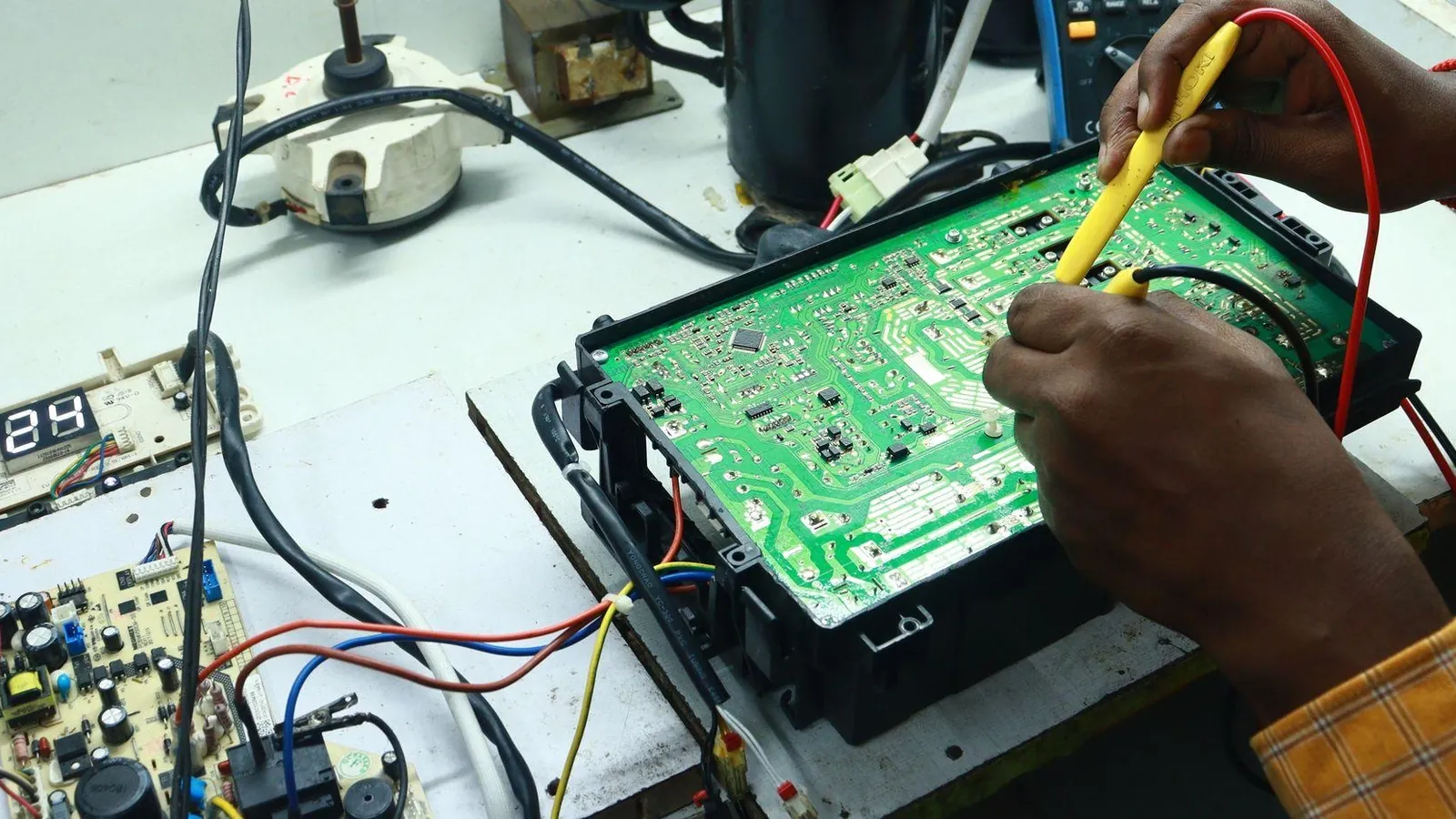
A mini split communication error fix will usually come down to three things: fixing the power, fixing the wiring or replacing a board that failed. Before you call anyone, you can check all three with a screwdriver, a flashlight and about 20 minutes. This guide will walk you through what to inspect, what to fix and where to stop.
Key Takeaways
-
Most communication errors between the indoor unit and outdoor unit can trace back to a tripped circuit breaker, terminals that are wired wrong, or a loose connection. Check power first, then wiring.
-
Error codes show communication issues in mini split systems, but the same code can mean different problems on different brands. Error codes help you diagnose problems quickly only when you match the code to your specific model's manual or use an error-code tool to look it up.
-
Physical inspection of wiring and terminals is essential for troubleshooting communication errors. Many communication problems (wires that are backwards, loose terminals, wrong cable type) are safe for you to inspect and fix with basic tools.
-
Sealed refrigerant work, inverter board diagnostics and anything that involves live high voltage are not DIY tasks. Once you rule out wiring and power, call a technician.
-
Error codes and blink patterns vary by brand, so compare what you see on your display to your manual or a site like diyhvactools.com before assuming you know the fault.
What a Mini Split Communication Error Means
Even if both appear to have power, a communication error means the indoor and outdoor units can no longer exchange digital signals. The E0 code on many systems shows indoor and outdoor unit communication failure. Error codes can appear even if the system seems to be running fine on the surface.
What you usually see: a blank or flashing indoor display while the outdoor fan turns briefly then stops, an "EL 01" or "E1" code on the screen, or a repeating LED blink pattern on the outdoor control board. On many MRCOOL DIY 5th Gen units, code "EL 01" shows an indoor/outdoor communication error, even though the fan may still attempt to start.
Mini split systems exchange low-voltage data over communication wires that are dedicated to that purpose. Any interruption in that data link, whether an open wire, a short, polarity that is backwards or electrical noise, triggers the error. This applies to mini split AC systems in cooling mode and heat pump models in heating mode alike.
Communication Errors by Brand
Error codes are not standardized. The same "E1" shown on two different brands can point to completely unrelated problems, so error codes help diagnose problems quickly only when matched to the correct model.
Here is how a single code differs across factories:
| Code | Midea-built units | Gree-built units | TCL-built units |
|---|---|---|---|
| E1 | Communication error | High pressure protection | Room temperature sensor fault |
On MRCOOL DIY 5th Gen, "EL 01" is an indoor/outdoor communication error, while "EH 60" and "EH 61" are the room temperature sensor (T1) and indoor coil sensor (T2) faults. Those are sensor codes, not communication errors.
Pioneer WYT indoor units with an R-454B leak sensor add another layer. "Fd" is a serial communication error with the onboard leak sensor; "Hd" means the sensor actually detected refrigerant. The two codes look similar on the display but require completely different responses.
Because of this variety, always confirm code meanings against your model-specific manual or a current error-code database rather than guessing.
Typical Symptoms of Communication Issues
If you are seeing several of these at once, a communication error between the two units is very likely:
-
The indoor unit display shows a fault code or LEDs that blink. Outdoor unit never starts.
-
The indoor unit louver opens, but no cooling or heating follows before a fault code appears.
Some systems show communication trouble only through outdoor board LED blink codes. Check for a diagnostic sticker on the outdoor unit service cover that maps blink counts to faults.
Common Causes of Mini Split Communication Errors
Around 70-80% of communication problems a homeowner can influence are related to power or wiring between indoor and outdoor units. Common causes of communication errors include loose wiring and damaged wiring.
Wiring mistakes. Conductors landed on the wrong terminals that are numbered, polarity that is backwards between L and N, swapped communication and power wires, or indoor and outdoor terminal labels that do not match. Improper installation can block signals between the two units completely.
Cable and distance problems. Voltage drop on cable that is too small causes signal loss. Running low-voltage signal wires in the same conduit as 120/240 V lines picks up noise, especially on runs longer than 50-75 feet. Pioneer specifies AWG 16 x 4-core TC-ER cable for WYT models, carrying two power wires, one signal wire (the black wire or otherwise labeled conductor), and one ground.
Power supply faults. Communication errors occur when power supply issues prevent units from receiving power. A tripped circuit breaker, a blown fuse at the disconnect, or power fluctuations can cause temporary communication glitches. Power surges can interrupt communication connections outright.
Environmental damage. Rodent-chewed insulation, jackets damaged by UV, corroded connectors and water getting in at wall penetrations all degrade the link. The presence of corrosion on terminals can block signal transmission completely.
Safety Checks Before You Start Troubleshooting
Before you touch any wiring, you will need to kill the power. Turn off the mini split at the remote or wall controller, then switch off the dedicated breaker that is feeding the outdoor unit. If there is a disconnect switch near the outdoor unit, open that too.
Verify that the breaker is actually feeding the correct circuit. In a house with multiple units installed, it is easy to flip the wrong one.
If you are not comfortable using a screwdriver or basic multimeter, stop at visual checks and call a professional. EPA 608-licensed technicians are needed for any refrigerant work, so do not open service valves or disturb refrigerant piping while you are chasing communication problems. Inverter board components inside the outdoor unit can hold dangerous voltage even after shutdown.
Step-by-Step DIY Fixes for Communication Errors
-
Verify power. Check the breaker and reset any GFCI or disconnects. Check that power is getting to both the indoor and outdoor units. If you are qualified, confirm line voltage at the outdoor unit control board with a multimeter. Testing voltage and signal with a multimeter can diagnose communication issues that are invisible to the eye.
-
Inspect wiring for signs of damage or loose connections. Open the terminal covers on both units. Compare conductor positions to the wiring diagram on the outdoor unit service panel. Make sure the terminal order (1-2-3-ground or similar) is identical at both ends. Loose wiring leads to intermittent communication failures.
-
Tighten and clean. Gently tug each conductor to find wires that are partially clamped. Tighten terminal screws and re-make any connections that are darkened or corroded. Physical inspection of wiring and terminals catches most installation errors.
-
Remove nearby electronics that may interfere with signals. Move any large motors, generators or other high-frequency sources away from the communication cable path if possible.
-
Reset the system. Turn the breaker off for at least 30 seconds. A full 5-10 minutes is better for clearing latent faults in the microprocessors. A hard reset can clear temporary issues in the system's main PCB and indoor board. Restore power and command heating or cooling to see if the communication error clears.
When Wiring Causes Serial Communication Errors
Many serial communication error faults arise not from a broken wire but from noise or voltage drop that is corrupting the low-voltage data signal. Electromagnetic interference can corrupt data signals in mini split systems, and electronic interference from nearby equipment can disrupt signal transmission.
The communication cable should be copper, properly sized (often 14-4 or 16-4 gauge), and rated at 300-600 V. Many manufacturers need shielded stranded wire for their mini split systems. Generic low-voltage thermostat cable is not acceptable for most units because it lacks the voltage and ampacity rating the system components need. Using aluminum or mixed-metal conductors can cause intermittent faults over time as dissimilar metals corrode at the connection point.
Trace the cable route. Avoid running it in the same conduit as high-voltage feeds. If the long run exceeds about 75-100 feet, consider upsizing the conductor gauge or shortening the path, always following the manufacturer's maximum distance limits.
If a cable has visible damage, stiff or cracked insulation from sun exposure, or multiple splices, the most reliable solution is to pull a new, continuous communication cable between the inside unit and outdoor unit.
Problems Only a Technician Should Handle
These issues need a professional:
-
Indoor main PCB or outdoor inverter board failure, transformers that failed and low-voltage power supply faults. A blown fuse on the control board may show a short circuit or power surge that damaged components upstream.
-
Some boards lock out communication when they detect other faults first. Fujitsu units, for example, use a 10 + 4 blink pattern for high pressure errors and 10 + 5 for low pressure errors. Both can look like communication codes to a homeowner but point to refrigerant-side problems a pro must look at.
Document everything before the service visit: take photos of wiring, note exact error codes and blink patterns, record the outdoor ambient temperature, and log what mode the heat pump was in when the failure occurred. Documenting error codes for technician review during service cuts diagnostic time and cost.
Preventing Future Communication Errors
Seasonal checks: Confirm the outdoor unit is clear of debris. Inspect exposed wiring for damage from abrasion or animals. Tighten any accessible low-voltage terminals with power off. Regular check-ups catch potential issues early, before they cause significant disruptions during summer heat or winter cold. Inspecting electrical connections ensures stable communication through temperature swings.
Certain components have a design life. Pioneer WYT R-454B leak sensors, for instance, are rated for about 15 years. Very old equipment may need sensor or control upgrades to maintain reliable comfort and avoid recurring communication errors.
FAQ About Mini Split Communication Errors
Can I run my mini split with an occasional communication error?
Intermittent communication errors usually show a loose connection or marginal wiring. You can run the unit in the short term, but the fault will likely recur at the worst possible point, during extreme heat or cold when the system is under full load. Inspect terminals and cable routing soon. Do not ignore repeating communication issues even if the house feels comfortable right now.
Do I need 14-4 or 16-4 cable, or can I use thermostat wire?
Mini split communication wiring usually carries both power and data, so it must meet the manufacturer's voltage and ampacity ratings. Typical low-voltage thermostat cable does not meet those ratings and creates a fire risk. Check your installation manual. If it says to use something like "AWG 16, 4-core, 600 V rated copper," use that or better. Wrong cable is a common cause of communication problems that only shows up after the system has been connected for weeks or months.
How far can I run the communication cable?
Maximum distances vary by brand and model, but many residential mini split systems limit combined line-set and cable runs to around 50-100 feet before capacity and communication reliability start to drop. Check the engineering or installation manual for your exact model. If your existing run is near the maximum and you are having issues, a technician may need to move the units or adjust wiring.
Will a surge protector prevent communication errors?
A whole-home or dedicated surge protector will not fix bad wiring, but it can reduce damage to inverter boards and control electronics that might otherwise fail and display as communication errors. Have a licensed electrician handle the installation, especially for 240 V heat pump systems. A quick estimate from an electrician for a panel-mount surge protector usually runs less than the cost of replacing one inverter board.
Where can I find my error code meaning?
The best sources are the model-specific installation or service manual, the wiring diagram sticker on the outdoor unit access panel, and updated online error-code tools to look them up. Sites like diyhvactools.com pull together about 2,600 mini split error codes across 48 brands so you can identify whether a code is truly a communication error or something else before you start pulling wires apart.
Figures and specs above are as published in October 2026 and may change. Your own unit's installation manual and local code take precedence. Brand names are trademarks of their respective owners, and this site is not affiliated with them.